

Case study
SmartX Backup & Disaster Recovery
Research and design asynchronous replication feature from scratch.
role
Only designer
Platform
Web
My Contribution
UI / UX Design
Design Research
Background
SmartX Backup & Disaster Recovery is a function set that includes Backup and Replication (including asynchronous replication and synchronous replication).
Backup & Disaster Recovery is a new product line for us. In Backup 1.0, we launched backup and recovery capabilities to provide data backup, data recovery, and enterprise-grade data protection for data center workloads. It supports backup virtual machines running on the ELF platform to external NAS storage outside the cluster.
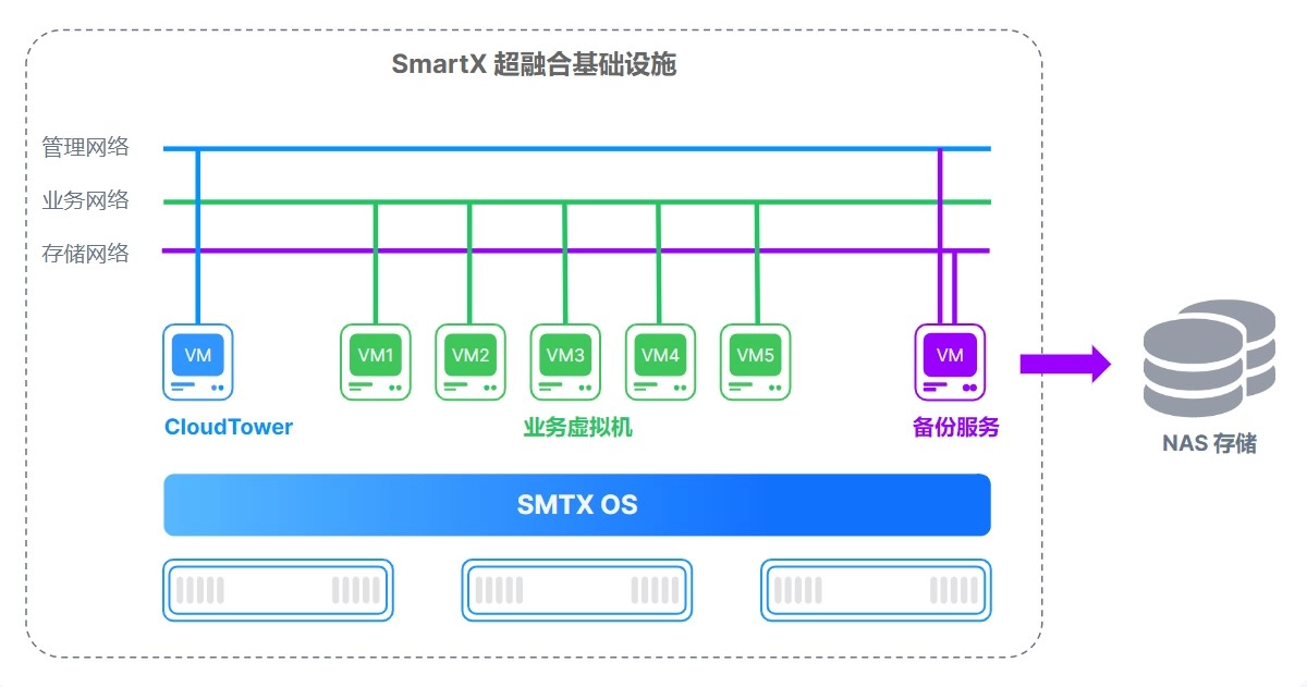
Backup 1.0 supports backing up virtual machines to external NAS storage.
Asynchronous Replication provides low recovery point objective (RPO) and low recovery time objective (RTO) block storage replication for cross-region active-passive disaster recovery (DR). Asynchronous Replication is a storage option that provides asynchronous replication of data between two regions. In the unlikely event of a regional outage, Asynchronous Replication lets you failover your data to a secondary region and restart your workload in that region.
Since version 2.0, we needed to build asynchronous replication, cross-site disaster recovery, volume replication support, and failover testing from the ground up. As the sole designer for the Backup & Disaster Recovery product line, I was responsible for designing this entire complex feature set.
This is the process I used to design a product in a completely new domain—from knowing nothing about the concept to delivering a complete solution.

Challenges
Starting from version 2.0, I took over the design of the Backup & Disaster Recovery product line. While I was still getting familiar with the existing product, new requirements came in. At the beginning, I did not know where to start.
Here were main challenges I was facing:
1. “Asynchronous replication” was a completely new domain for me.
When the product manager sent me a requirements document filled with over 40 pages of jargon(failover, failback, RPO, RTO), I was overwhelmed.
Although I had some understanding of disaster recovery, I knew very little about asynchronous replication. I needed to quickly build up my knowledge in this area so I could start the product design work as soon as possible.
2. The system is highly complex, and a single feature can have an impact across the entire system.
The SMTX OS product is a highly integrated system with many interconnected modules, so adding a new feature can affect many other parts of the system.
- PermissionsSMTX OS provides flexible, role-based access control. Whenever a new feature is introduced, the corresponding permission toggle must also be added to the user permission settings.
- DashboardReplication plan statuses and information about protected resources need to be displayed on the Backup & Disaster Recovery dashboard.
- Resource ListsReplication plan–related fields need to be added to the cluster lists and virtual machine lists.
- Events & Task CenterEvery user action and system operation related to replication is recorded as an event. For asynchronous tasks, notifications and status feedback are provided in the Task Center.
Design Process
Before we dived into the "design" job, we spent about 3 weeks on doing user researches. We believe that we can only come up with good design solutions when truly understand client's problems.
1. Research
After reviewing the PRD, I still didn't fully understand the requirements for "asynchronous replication," so I started with research. So I spent a lot of time on doing researches, including several rounds of 1:1 interviews and competitive research.
1:1 interviewsWe conducted several rounds of interviews with product manager, engineers, and sales. I asked questions about:
- their current DR workflow.
- What were they struggling with?
- Which other backup and disaster recovery products are currently in use?
- What are the key features and advantages of the backup and disaster recovery product we plan to launch compared with other products?
- ...
Competitive researchWe also did some competitive researches on similar disaster recovery products(Including Veeam, Nutanix, Zerto, vSphere).
- What were the solutions these products provide?
- What did their workflow look like?
- What were the pros and cons of them?
- How does it differ from our product roadmap?
- ...
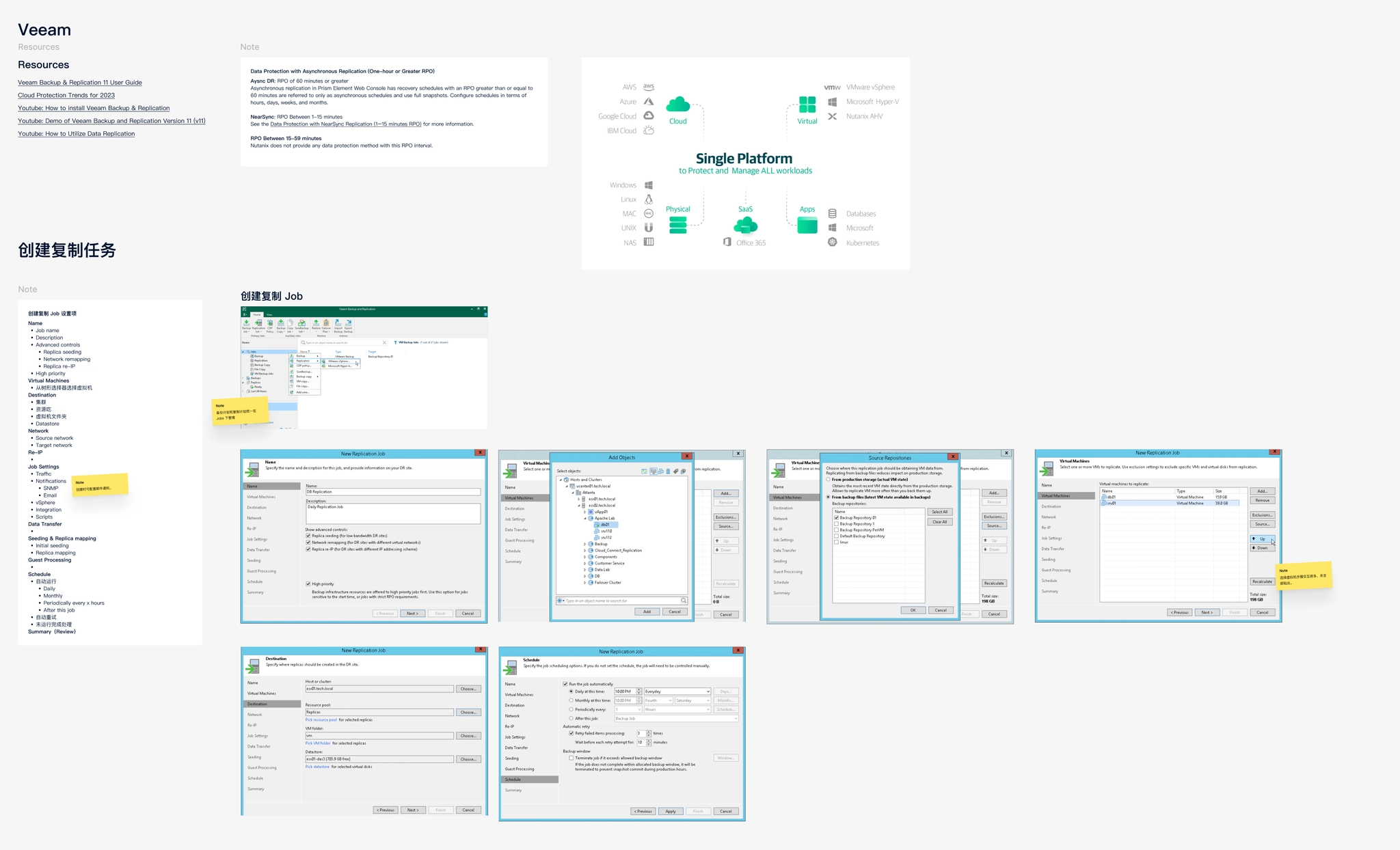
Design research on Veeam’s DR feature
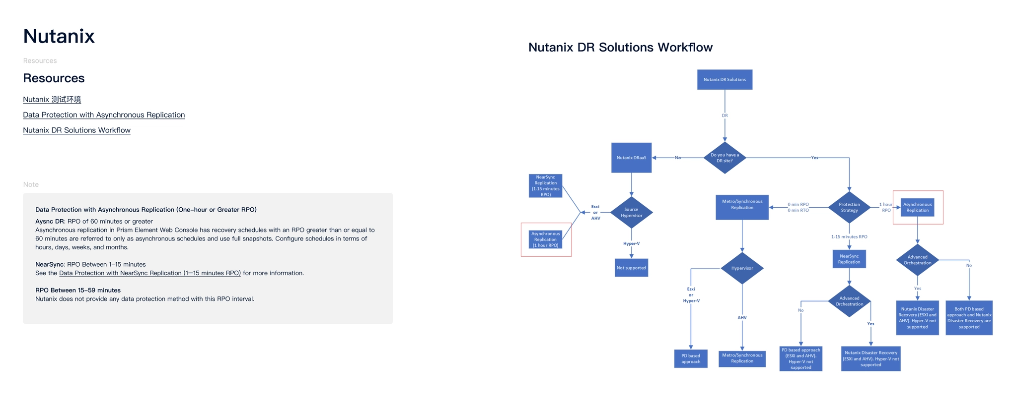
Design research on Nutanix’s DR workflow
2. Analyze
After gathering enough information I need, I started to analyze them and turned them into insights.
We chose to use a storyboard and a press release (Amazon’s Working Backwards approach) to illustrate the customer problems, and how our asynchronous replication feature would solve the problems and the goals it was designed to achieve.
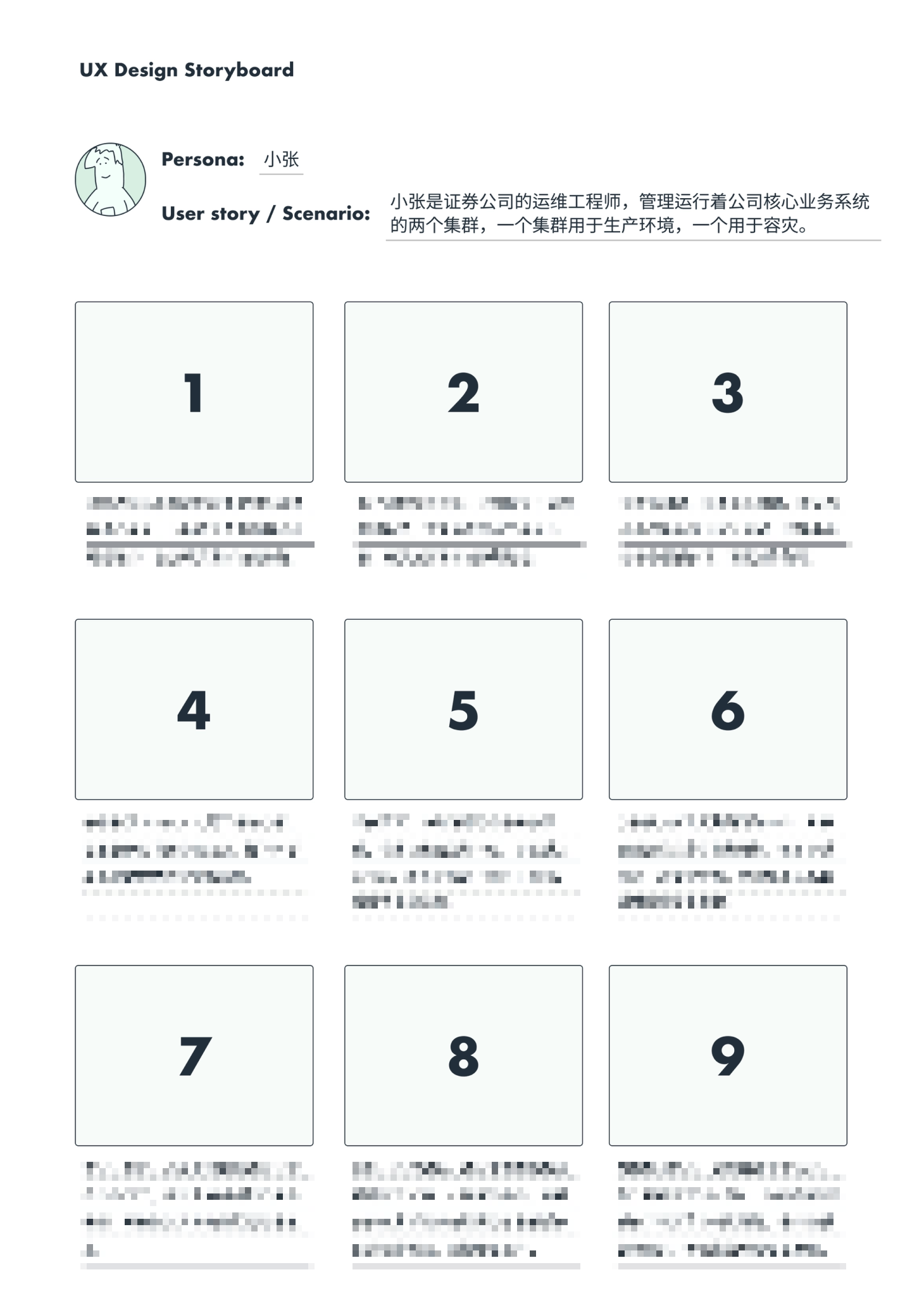
Replication storyboard
Replication press release
Then I began breaking this complex requirement down into smaller, self-contained modules, and used them as the foundation for the prototype and UI design.
Create a Replication Plan
- Enter basic information
- Set the replication schedule
- Configure the retention policy
- Configure the replica VM
Replication Plan Information
- Replication plan table
- Replication plan details
- Replicated objects table
- Backup & Disaster Recovery overview
Failover OperationsSupports both single-VM and bulk operations
- Failover
- Failback
- Permanent Failover
Other
- Installation and deployment workflow
- Feature management
- Events, Task Center
- Permissions
- Impact on the cluster list and VM list
- …
3. Design exploration
Finally, we moved into the design phase. I started by building low-fidelity prototypes, first creating a happy path prototype that covered the key screens and the complete flow for creating a replication plan, performing failback, and executing failover.
Happy path prototype
Once prototype was completed, I shared it with the team to gather feedback, and continued refining the solution through an iterative cycle of optimization → gather feedback → iteration.
After few rounds of iteration, we finalized the overall design solution.
4. Refining the UI Design
After completing the prototype design, I shifted my focus to the UI design phase, defining the previously unresolved parts of the design and refining key pages.
4.1 Source VM vs. Replica VM
After a virtual machine is added to a replication plan, a replica VM is created in the target cluster. On the Replication Plan Details page and the Replicated Objects page, I needed to consider how to clearly represent both the source VM and the replica VM.
To address this, I designed a connected-line UI to visually convey the relationship between the VMs. I also introduced status indicators for the VMs: under normal conditions, the source VM remains powered on; when the source VM fails, the replica VM takes over, at which point the source VM is powered off and the replica VM becomes powered on. These status indicators are displayed in the bottom-right corner of the source VM and replica VM icons.
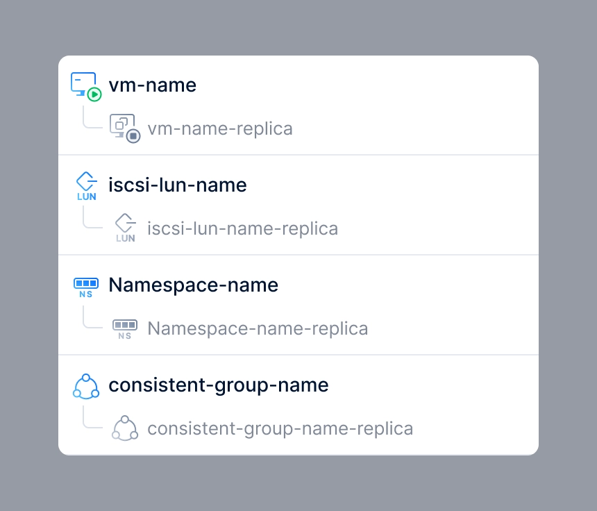
The connected-line UI convey the relationship between source VM & replica VM.
The design used in replication plan detail page and replica objects page.
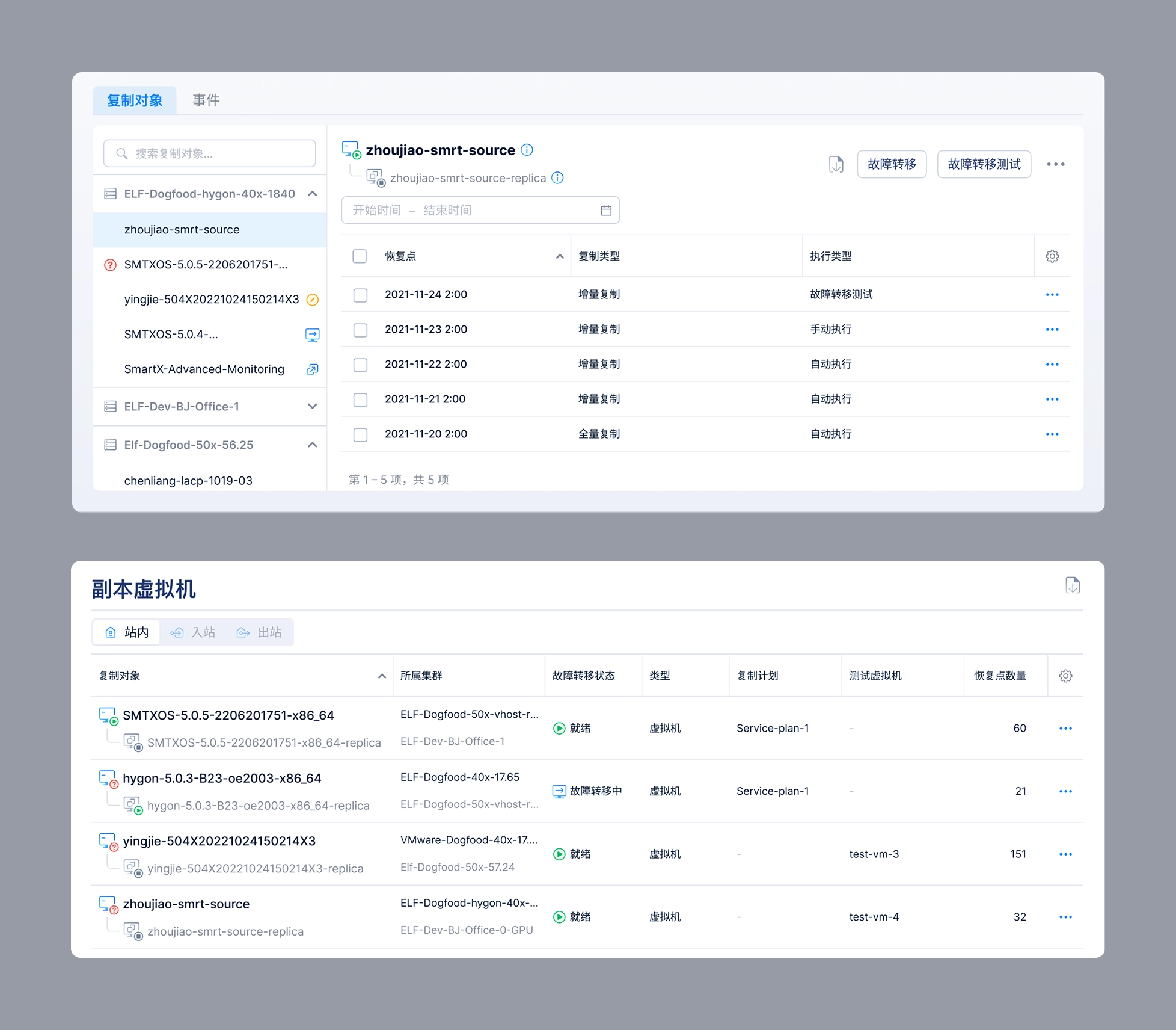
4.2 Replication plan detail
The Replication Plan Details page needs to display not only the basic information of the replication plan, but also the VMs included in the plan.
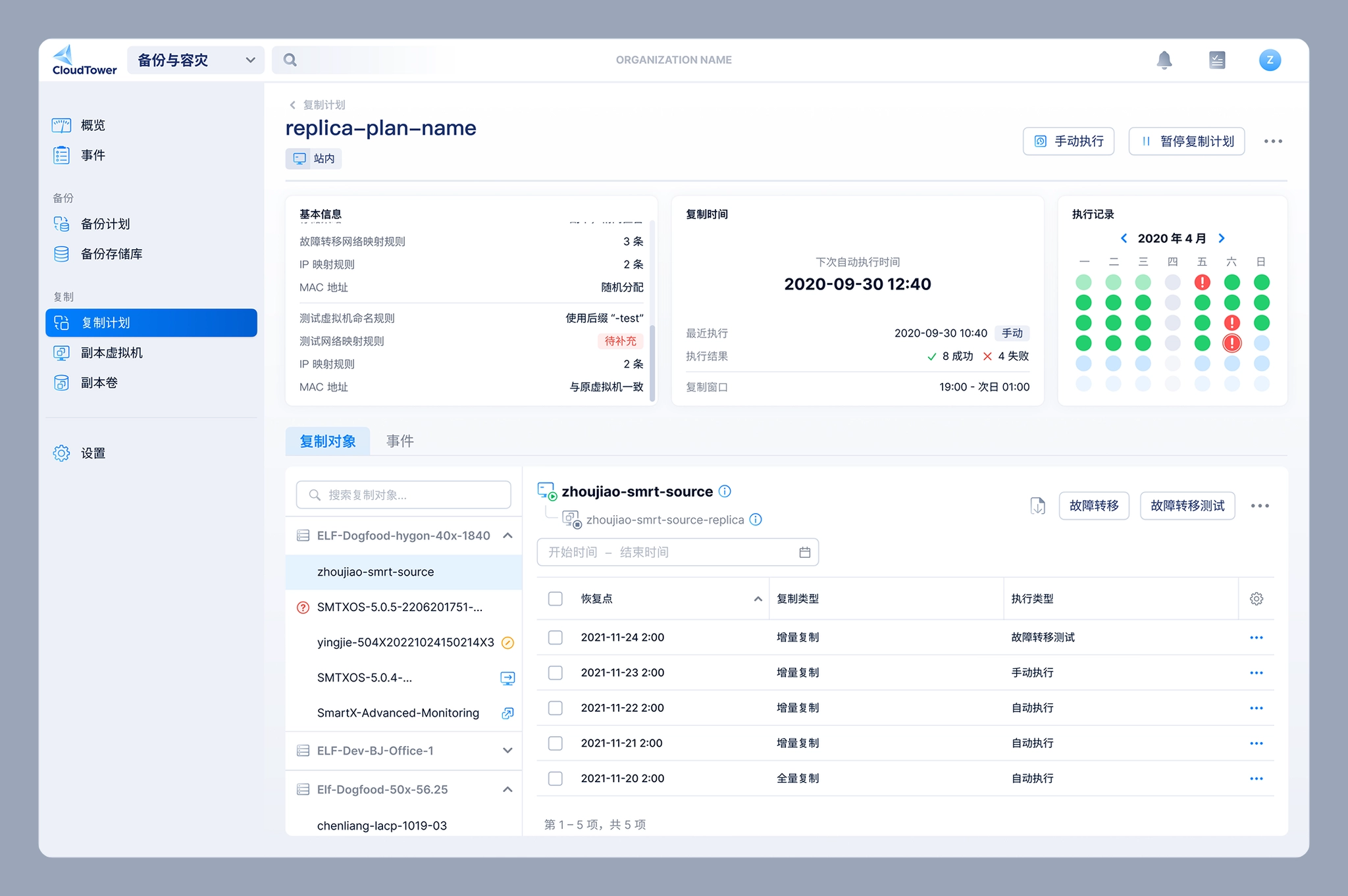
Replication plan detail page
One of the biggest design challenges on the Replication Plan Details page was how to clearly communicate the status of the virtual machines included in a replication plan. These statuses were relatively complex and could be grouped into three categories:
- VM runtime status: Powered On, Powered Off, and Paused
- VM exception status: Unknown and Deleted
- Failover status: Not Ready (failover unavailable), Ready (failover available), Failing Over, Replicating (data is being replicated from the source VM to the replica VM), and Failing Back (data is being restored from the replica VM to the source VM)
After several days of design exploration, I finalized the solution:
- I designed a dedicated icon for each failover status, except for Ready.
- Exception statuses are displayed to the left of the VM name, while failover statuses appear on the right.
- When a VM is selected, its detailed status information is displayed in the right-hand panel.
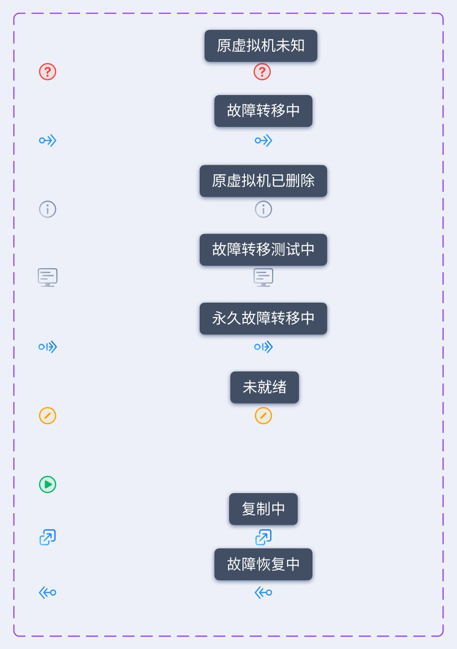
VM’s status in a replication plan.
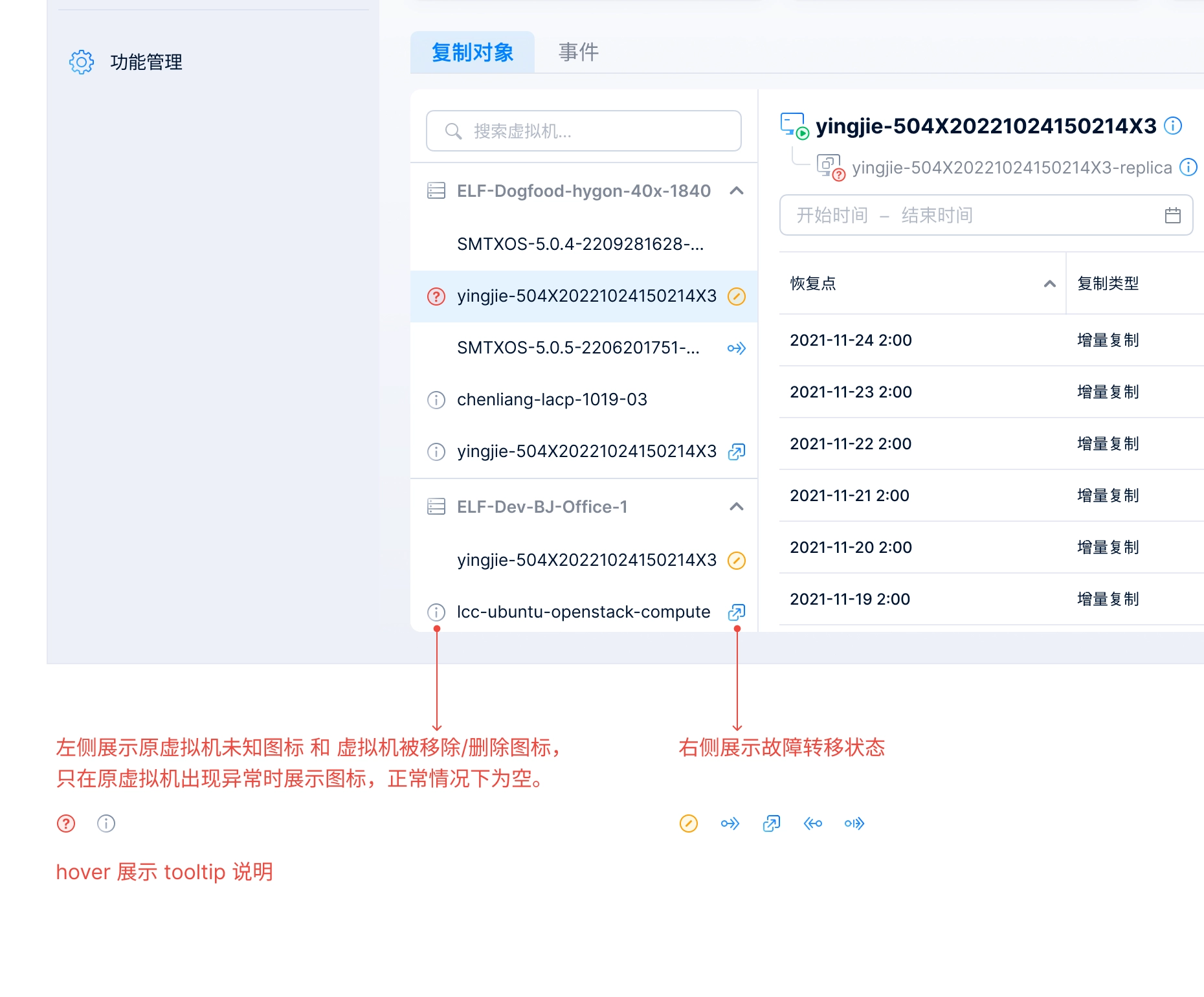
UI spec of different status.
4.3 Logo design
After completing the overall UI spec for the feature, I started designing a logo for Backup & Disaster Recovery, which would be displayed in the feature list and on the product introduction page of the website.
In the end, we chose Option C for the following reasons:
- The first two icons both include a virtual machine visual, which could mislead users into thinking that the feature only supports virtual machines. This would also limit how well the logo scales for future expansion(Support adding volumes to replication plan).
- Option C better represents the core mechanism of disaster recovery and works well for both backup and replication features.
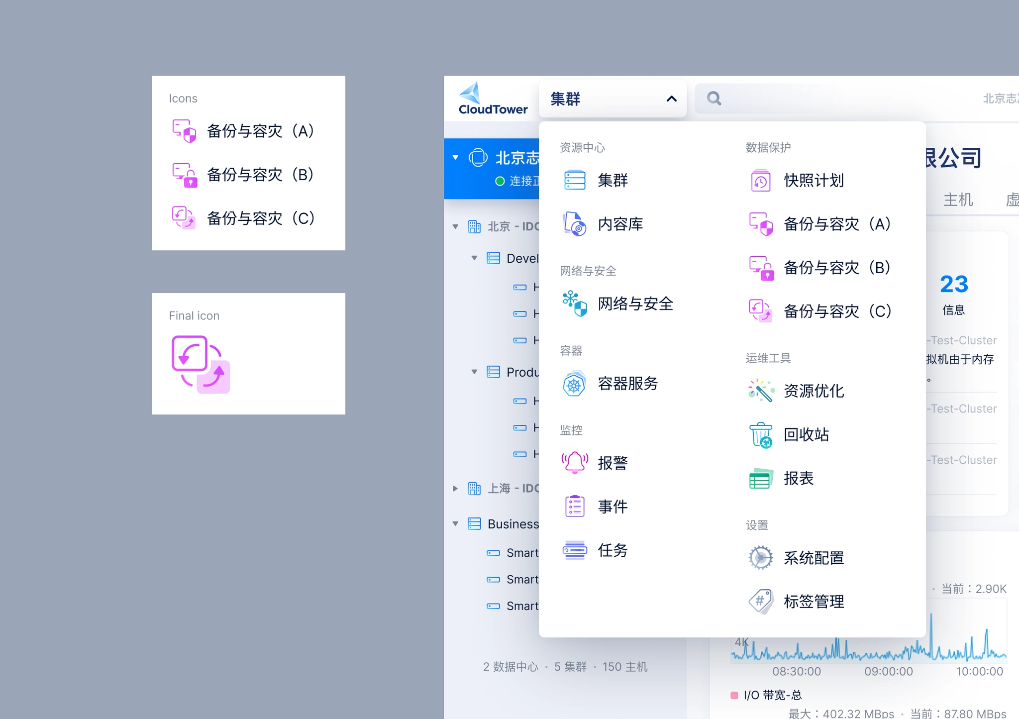
Logo options for Backup & Disaster Recovery.
5. Writing UI specs
This was probably the most time-consuming step and the one that required the greatest attention to detail. I wrote detailed design specifications for every component across each newly introduced UI screen, covering interaction behaviors, value ranges, default states, dependencies between components, relationships to resource states, and how the system should respond to cluster or service exceptions. Everything needed to be clearly documented in the UI spec so the design could be handed off to engineering for implementation.
Below are UI spec examples for several pages.
UI spec examples
UI spec examples
UI spec examples
Once prototype was completed, I shared it with the team to gather feedback, and continued refining the solution through an iterative cycle of optimization → gather feedback → iteration.
After few rounds of iteration, we finalized the overall design solution.
6. Maintaining the Design System
6.1 Resource Selector Component
When creating a replication plan, users need to select VMs or volumes to include in the plan. The resource selector is also used in other scenarios, such as creating snapshot plans, backup plans, or any workflow that involves selecting resources.
Resource Selector for VM
Resource Selector for volume
For this reason, I packaged the resource selector into a reusable UI component so other designers could easily apply it across different features, while also ensuring a consistent user experience throughout SMTX OS.
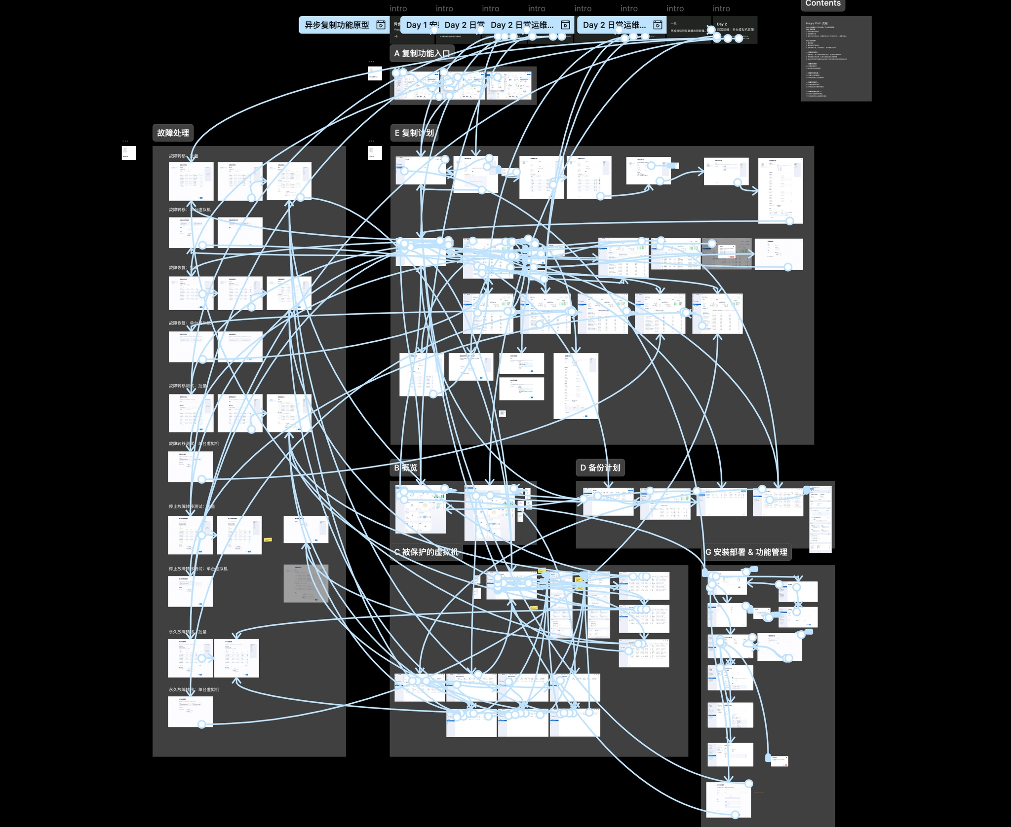
6.2 Replication UI Map
The asynchronous replication feature involved many different branches:
By site scope:
- Intra-site replication
- Cross-site replication
- Outbound
- Inbound
By protected resource type:
- VMs
- Volumes: iSCSI, Namespace, and Consistency Group
Each page displays different data depending on the scenario, which can result in many possible combinations of states.
Design pages index in UI Map
To make this easier for the team to review, I created a Replication UI Map to organize the different states across each screen.
Things I learned
Don’t be intimidated by a complex new requirement.
Start with research to understand the concepts and the customer problems that need to be solved. User research is an effective way to help you understand the problems.
Then break the complexity down into smaller modules—once you tackle them one by one, the design process becomes much more manageable.
Navigation


Case study
SmartX Backup & Disaster Recovery
Research and design asynchronous replication feature from scratch.
role
Only designer
Platform
Web
My Contribution
UI / UX Design
Design Research
Background
SmartX Backup & Disaster Recovery is a function set that includes Backup and Replication (including asynchronous replication and synchronous replication).
Backup & Disaster Recovery is a new product line for us. In Backup 1.0, we launched backup and recovery capabilities to provide data backup, data recovery, and enterprise-grade data protection for data center workloads. It supports backup virtual machines running on the ELF platform to external NAS storage outside the cluster.
Backup 1.0 supports backing up virtual machines to external NAS storage.
Asynchronous Replication provides low recovery point objective (RPO) and low recovery time objective (RTO) block storage replication for cross-region active-passive disaster recovery (DR). Asynchronous Replication is a storage option that provides asynchronous replication of data between two regions. In the unlikely event of a regional outage, Asynchronous Replication lets you failover your data to a secondary region and restart your workload in that region.
Since version 2.0, we needed to build asynchronous replication, cross-site disaster recovery, volume replication support, and failover testing from the ground up. As the sole designer for the Backup & Disaster Recovery product line, I was responsible for designing this entire complex feature set.
This is the process I used to design a product in a completely new domain—from knowing nothing about the concept to delivering a complete solution.

Challenges
Starting from version 2.0, I took over the design of the Backup & Disaster Recovery product line. While I was still getting familiar with the existing product, new requirements came in. At the beginning, I did not know where to start.
Here were main challenges I was facing:
1. “Asynchronous replication” was a completely new domain for me.
When the product manager sent me a requirements document filled with over 40 pages of jargon(failover, failback, RPO, RTO), I was overwhelmed.
Although I had some understanding of disaster recovery, I knew very little about asynchronous replication. I needed to quickly build up my knowledge in this area so I could start the product design work as soon as possible.
2. The system is highly complex, and a single feature can have an impact across the entire system.
The SMTX OS product is a highly integrated system with many interconnected modules, so adding a new feature can affect many other parts of the system.
- PermissionsSMTX OS provides flexible, role-based access control. Whenever a new feature is introduced, the corresponding permission toggle must also be added to the user permission settings.
- DashboardReplication plan statuses and information about protected resources need to be displayed on the Backup & Disaster Recovery dashboard.
- Resource ListsReplication plan–related fields need to be added to the cluster lists and virtual machine lists.
- Events & Task CenterEvery user action and system operation related to replication is recorded as an event. For asynchronous tasks, notifications and status feedback are provided in the Task Center.
Design Process
Before we dived into the "design" job, we spent about 3 weeks on doing user researches. We believe that we can only come up with good design solutions when truly understand client's problems.
1. Research
After reviewing the PRD, I still didn't fully understand the requirements for "asynchronous replication," so I started with research. So I spent a lot of time on doing researches, including several rounds of 1:1 interviews and competitive research.
1:1 interviewsWe conducted several rounds of interviews with product manager, engineers, and sales. I asked questions about:
- their current DR workflow.
- What were they struggling with?
- Which other backup and disaster recovery products are currently in use?
- What are the key features and advantages of the backup and disaster recovery product we plan to launch compared with other products?
- ...
Competitive researchWe also did some competitive researches on similar disaster recovery products(Including Veeam, Nutanix, Zerto, vSphere).
- What were the solutions these products provide?
- What did their workflow look like?
- What were the pros and cons of them?
- How does it differ from our product roadmap?
- ...
Design research on Veeam’s DR feature
Design research on Nutanix’s DR workflow
2. Analyze
After gathering enough information I need, I started to analyze them and turned them into insights.
We chose to use a storyboard and a press release (Amazon’s Working Backwards approach) to illustrate the customer problems, and how our asynchronous replication feature would solve the problems and the goals it was designed to achieve.
Replication storyboard
Replication press release
Then I began breaking this complex requirement down into smaller, self-contained modules, and used them as the foundation for the prototype and UI design.
Create a Replication Plan
- Enter basic information
- Set the replication schedule
- Configure the retention policy
- Configure the replica VM
Replication Plan Information
- Replication plan table
- Replication plan details
- Replicated objects table
- Backup & Disaster Recovery overview
Failover OperationsSupports both single-VM and bulk operations
- Failover
- Failback
- Permanent Failover
Other
- Installation and deployment workflow
- Feature management
- Events, Task Center
- Permissions
- Impact on the cluster list and VM list
- …
3. Design exploration
Finally, we moved into the design phase. I started by building low-fidelity prototypes, first creating a happy path prototype that covered the key screens and the complete flow for creating a replication plan, performing failback, and executing failover.
Happy path prototype
Once prototype was completed, I shared it with the team to gather feedback, and continued refining the solution through an iterative cycle of optimization → gather feedback → iteration.
After few rounds of iteration, we finalized the overall design solution.
4. Refining the UI Design
After completing the prototype design, I shifted my focus to the UI design phase, defining the previously unresolved parts of the design and refining key pages.
4.1 Source VM vs. Replica VM
After a virtual machine is added to a replication plan, a replica VM is created in the target cluster. On the Replication Plan Details page and the Replicated Objects page, I needed to consider how to clearly represent both the source VM and the replica VM.
To address this, I designed a connected-line UI to visually convey the relationship between the VMs. I also introduced status indicators for the VMs: under normal conditions, the source VM remains powered on; when the source VM fails, the replica VM takes over, at which point the source VM is powered off and the replica VM becomes powered on. These status indicators are displayed in the bottom-right corner of the source VM and replica VM icons.
The connected-line UI convey the relationship between source VM & replica VM.
The design used in replication plan detail page and replica objects page.
4.2 Replication plan detail
The Replication Plan Details page needs to display not only the basic information of the replication plan, but also the VMs included in the plan.
Replication plan detail page
One of the biggest design challenges on the Replication Plan Details page was how to clearly communicate the status of the virtual machines included in a replication plan. These statuses were relatively complex and could be grouped into three categories:
- VM runtime status: Powered On, Powered Off, and Paused
- VM exception status: Unknown and Deleted
- Failover status: Not Ready (failover unavailable), Ready (failover available), Failing Over, Replicating (data is being replicated from the source VM to the replica VM), and Failing Back (data is being restored from the replica VM to the source VM)
After several days of design exploration, I finalized the solution:
- I designed a dedicated icon for each failover status, except for Ready.
- Exception statuses are displayed to the left of the VM name, while failover statuses appear on the right.
- When a VM is selected, its detailed status information is displayed in the right-hand panel.
VM’s status in a replication plan.
UI spec of different status.
4.3 Logo design
After completing the overall UI spec for the feature, I started designing a logo for Backup & Disaster Recovery, which would be displayed in the feature list and on the product introduction page of the website.
In the end, we chose Option C for the following reasons:
- The first two icons both include a virtual machine visual, which could mislead users into thinking that the feature only supports virtual machines. This would also limit how well the logo scales for future expansion(Support adding volumes to replication plan).
- Option C better represents the core mechanism of disaster recovery and works well for both backup and replication features.
Logo options for Backup & Disaster Recovery.
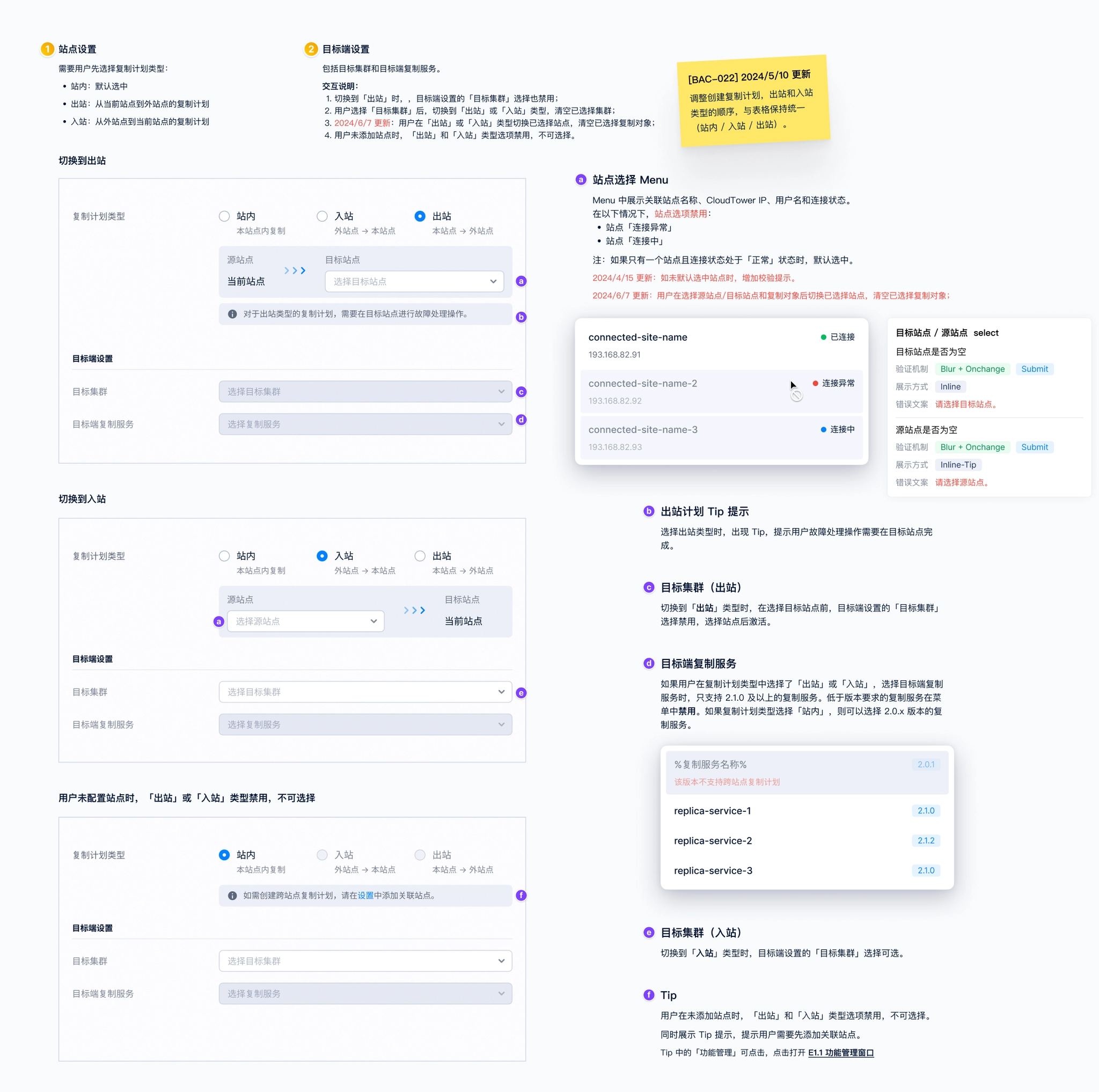
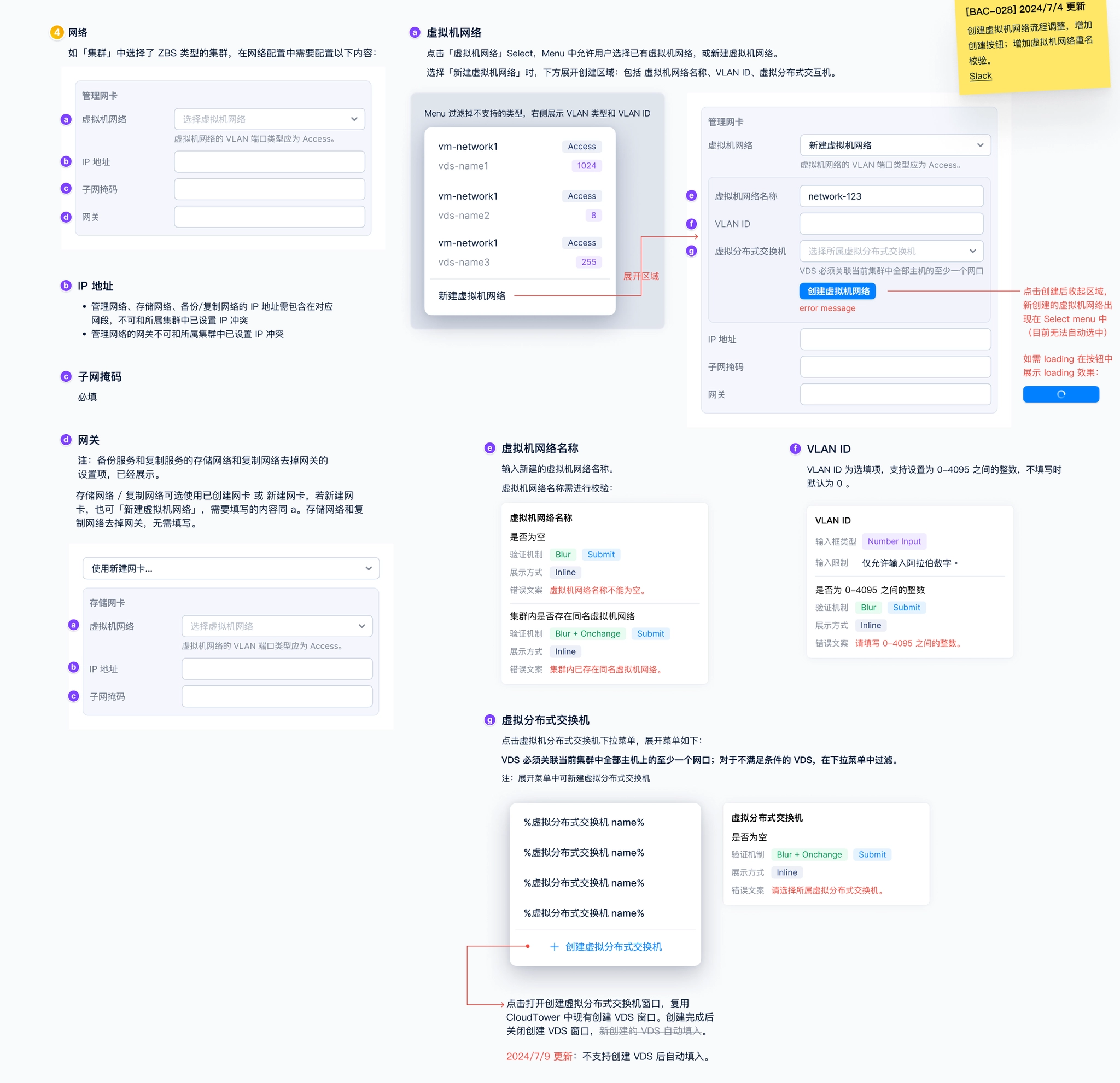
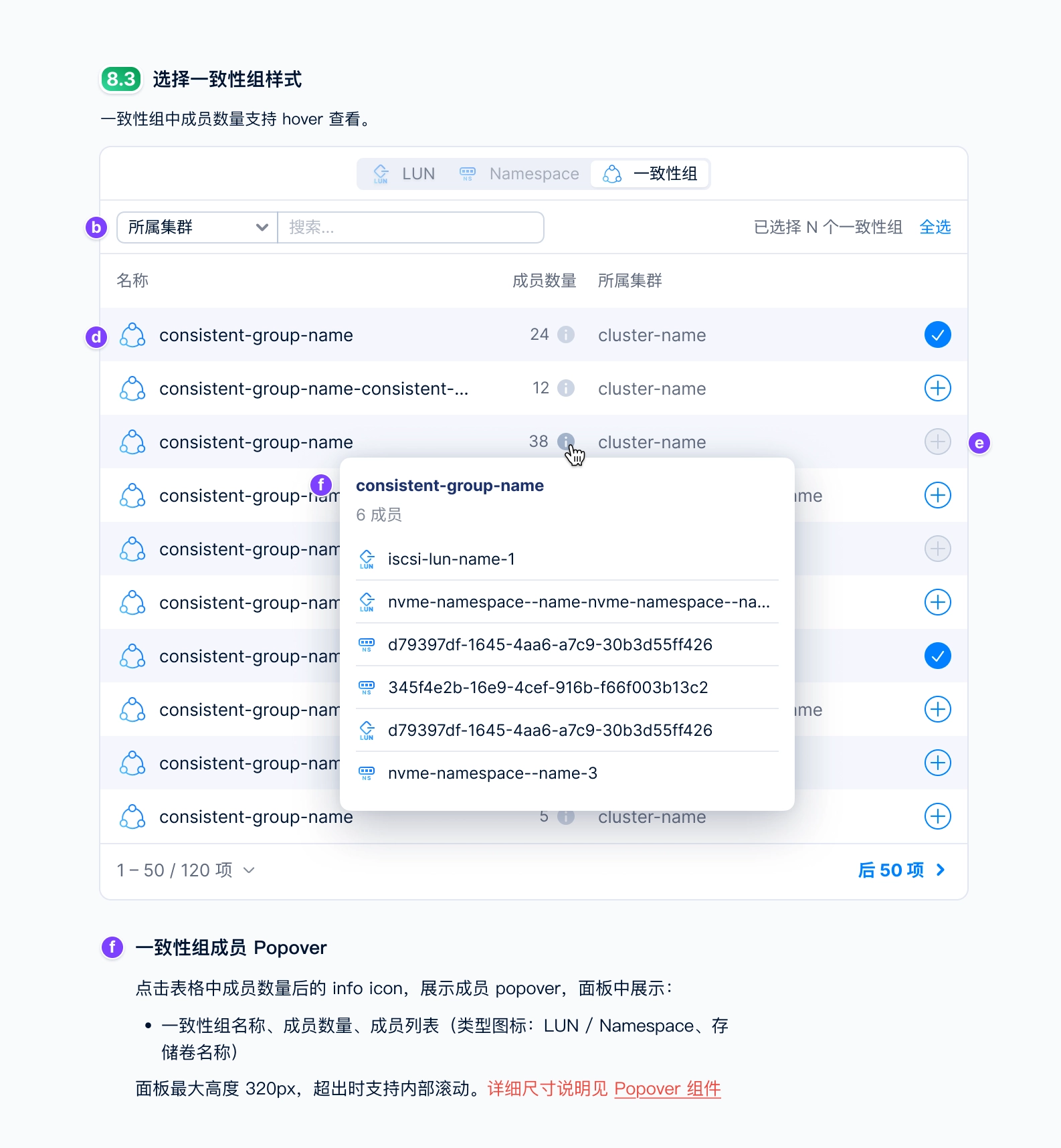
5. Writing UI specs
This was probably the most time-consuming step and the one that required the greatest attention to detail. I wrote detailed design specifications for every component across each newly introduced UI screen, covering interaction behaviors, value ranges, default states, dependencies between components, relationships to resource states, and how the system should respond to cluster or service exceptions. Everything needed to be clearly documented in the UI spec so the design could be handed off to engineering for implementation.
Below are UI spec examples for several pages.
UI spec examples
UI spec examples
UI spec examples
Once prototype was completed, I shared it with the team to gather feedback, and continued refining the solution through an iterative cycle of optimization → gather feedback → iteration.
After few rounds of iteration, we finalized the overall design solution.
6. Maintaining the Design System
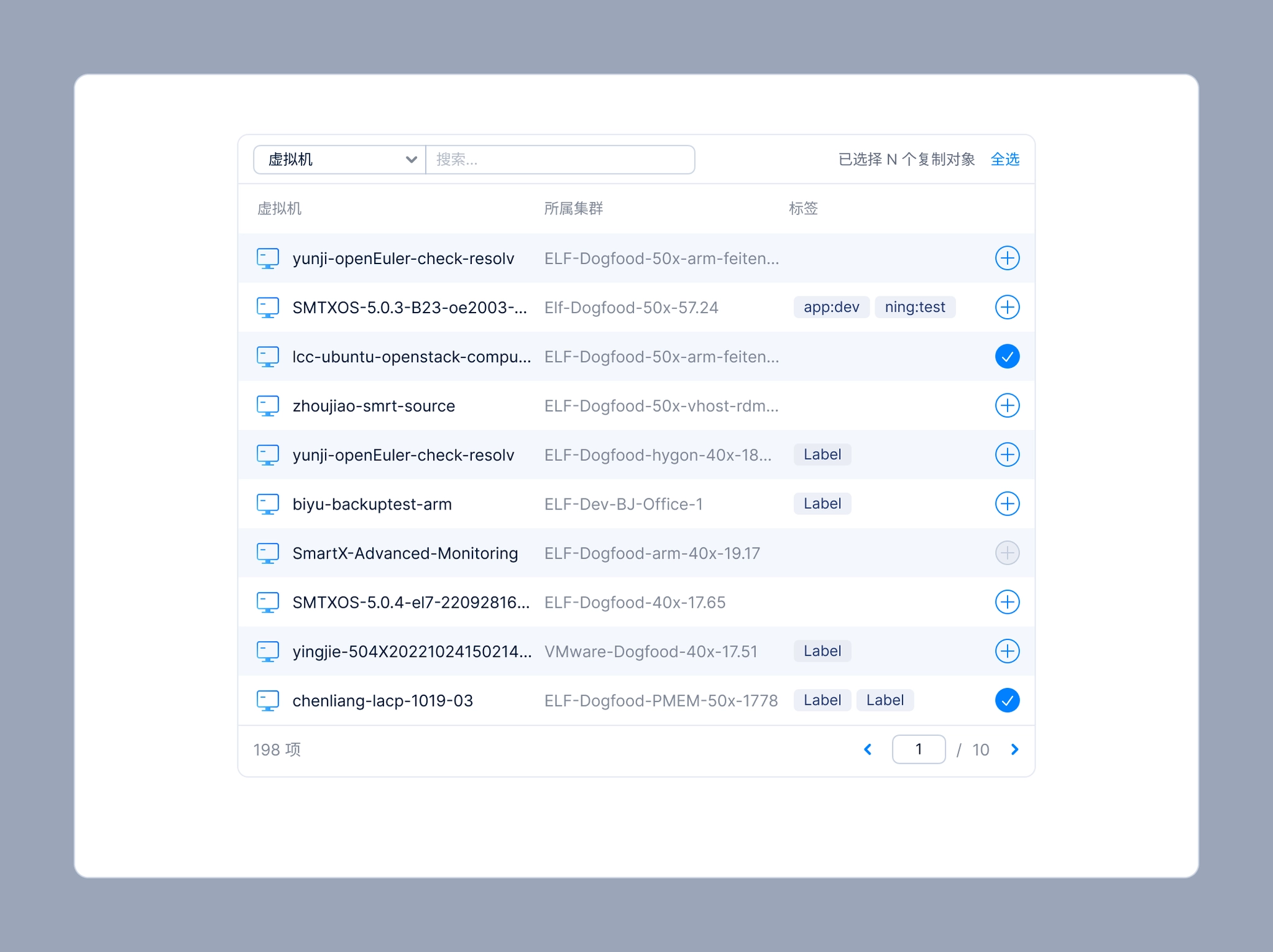
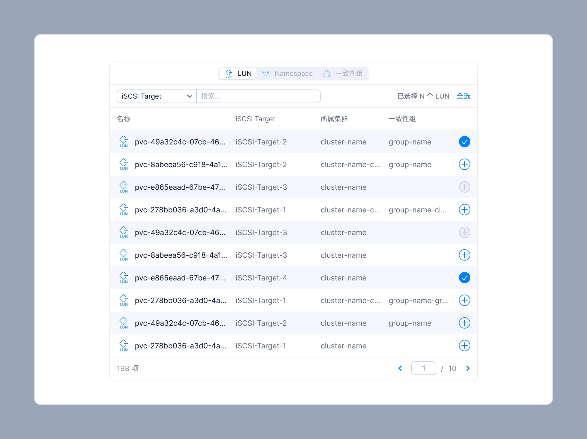
6.1 Resource Selector Component
When creating a replication plan, users need to select VMs or volumes to include in the plan. The resource selector is also used in other scenarios, such as creating snapshot plans, backup plans, or any workflow that involves selecting resources.
Resource Selector for VM
Resource Selector for volume
For this reason, I packaged the resource selector into a reusable UI component so other designers could easily apply it across different features, while also ensuring a consistent user experience throughout SMTX OS.
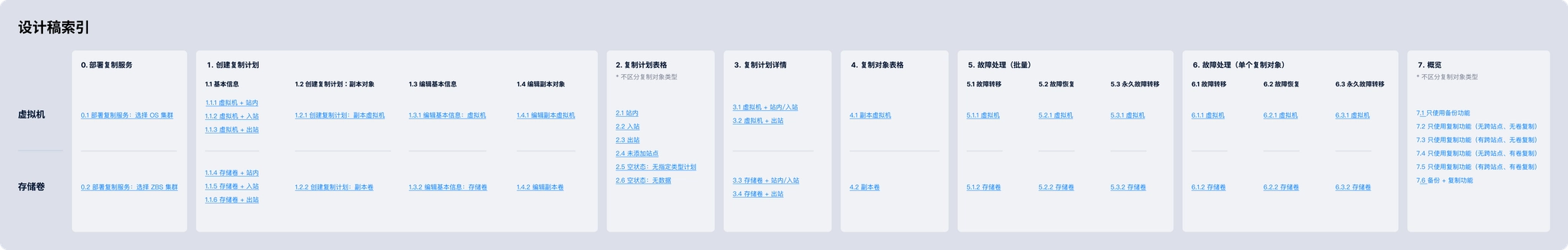
6.2 Replication UI Map
The asynchronous replication feature involved many different branches:
By site scope:
- Intra-site replication
- Cross-site replication
- Outbound
- Inbound
By protected resource type:
- VMs
- Volumes: iSCSI, Namespace, and Consistency Group
Each page displays different data depending on the scenario, which can result in many possible combinations of states.
Design pages index in UI Map
To make this easier for the team to review, I created a Replication UI Map to organize the different states across each screen.
Things I learned
Don’t be intimidated by a complex new requirement.
Start with research to understand the concepts and the customer problems that need to be solved. User research is an effective way to help you understand the problems.
Then break the complexity down into smaller modules—once you tackle them one by one, the design process becomes much more manageable.
Navigation


Case study
SmartX Backup & Disaster Recovery
Research and design asynchronous replication feature from scratch.
role
Only designer
Platform
Web
My Contribution
UI / UX Design
Design Research
Background
SmartX Backup & Disaster Recovery is a function set that includes Backup and Replication (including asynchronous replication and synchronous replication).
Backup & Disaster Recovery is a new product line for us. In Backup 1.0, we launched backup and recovery capabilities to provide data backup, data recovery, and enterprise-grade data protection for data center workloads. It supports backup virtual machines running on the ELF platform to external NAS storage outside the cluster.
Backup 1.0 supports backing up virtual machines to external NAS storage.
Asynchronous Replication provides low recovery point objective (RPO) and low recovery time objective (RTO) block storage replication for cross-region active-passive disaster recovery (DR). Asynchronous Replication is a storage option that provides asynchronous replication of data between two regions. In the unlikely event of a regional outage, Asynchronous Replication lets you failover your data to a secondary region and restart your workload in that region.
Since version 2.0, we needed to build asynchronous replication, cross-site disaster recovery, volume replication support, and failover testing from the ground up. As the sole designer for the Backup & Disaster Recovery product line, I was responsible for designing this entire complex feature set.
This is the process I used to design a product in a completely new domain—from knowing nothing about the concept to delivering a complete solution.

Challenges
Starting from version 2.0, I took over the design of the Backup & Disaster Recovery product line. While I was still getting familiar with the existing product, new requirements came in. At the beginning, I did not know where to start.
Here were main challenges I was facing:
1. “Asynchronous replication” was a completely new domain for me.
When the product manager sent me a requirements document filled with over 40 pages of jargon(failover, failback, RPO, RTO), I was overwhelmed.
Although I had some understanding of disaster recovery, I knew very little about asynchronous replication. I needed to quickly build up my knowledge in this area so I could start the product design work as soon as possible.
2. The system is highly complex, and a single feature can have an impact across the entire system.
The SMTX OS product is a highly integrated system with many interconnected modules, so adding a new feature can affect many other parts of the system.
- PermissionsSMTX OS provides flexible, role-based access control. Whenever a new feature is introduced, the corresponding permission toggle must also be added to the user permission settings.
- DashboardReplication plan statuses and information about protected resources need to be displayed on the Backup & Disaster Recovery dashboard.
- Resource ListsReplication plan–related fields need to be added to the cluster lists and virtual machine lists.
- Events & Task CenterEvery user action and system operation related to replication is recorded as an event. For asynchronous tasks, notifications and status feedback are provided in the Task Center.
Design Process
Before we dived into the "design" job, we spent about 3 weeks on doing user researches. We believe that we can only come up with good design solutions when truly understand client's problems.
1. Research
After reviewing the PRD, I still didn't fully understand the requirements for "asynchronous replication," so I started with research. So I spent a lot of time on doing researches, including several rounds of 1:1 interviews and competitive research.
1:1 interviewsWe conducted several rounds of interviews with product manager, engineers, and sales. I asked questions about:
- their current DR workflow.
- What were they struggling with?
- Which other backup and disaster recovery products are currently in use?
- What are the key features and advantages of the backup and disaster recovery product we plan to launch compared with other products?
- ...
Competitive researchWe also did some competitive researches on similar disaster recovery products(Including Veeam, Nutanix, Zerto, vSphere).
- What were the solutions these products provide?
- What did their workflow look like?
- What were the pros and cons of them?
- How does it differ from our product roadmap?
- ...
Design research on Veeam’s DR feature
Design research on Nutanix’s DR workflow
2. Analyze
After gathering enough information I need, I started to analyze them and turned them into insights.
We chose to use a storyboard and a press release (Amazon’s Working Backwards approach) to illustrate the customer problems, and how our asynchronous replication feature would solve the problems and the goals it was designed to achieve.
Replication storyboard
Replication press release
Then I began breaking this complex requirement down into smaller, self-contained modules, and used them as the foundation for the prototype and UI design.
Create a Replication Plan
- Enter basic information
- Set the replication schedule
- Configure the retention policy
- Configure the replica VM
Replication Plan Information
- Replication plan table
- Replication plan details
- Replicated objects table
- Backup & Disaster Recovery overview
Failover OperationsSupports both single-VM and bulk operations
- Failover
- Failback
- Permanent Failover
Other
- Installation and deployment workflow
- Feature management
- Events, Task Center
- Permissions
- Impact on the cluster list and VM list
- …
3. Design exploration
Finally, we moved into the design phase. I started by building low-fidelity prototypes, first creating a happy path prototype that covered the key screens and the complete flow for creating a replication plan, performing failback, and executing failover.
Happy path prototype
Once prototype was completed, I shared it with the team to gather feedback, and continued refining the solution through an iterative cycle of optimization → gather feedback → iteration.
After few rounds of iteration, we finalized the overall design solution.
4. Refining the UI Design
After completing the prototype design, I shifted my focus to the UI design phase, defining the previously unresolved parts of the design and refining key pages.
4.1 Source VM vs. Replica VM
After a virtual machine is added to a replication plan, a replica VM is created in the target cluster. On the Replication Plan Details page and the Replicated Objects page, I needed to consider how to clearly represent both the source VM and the replica VM.
To address this, I designed a connected-line UI to visually convey the relationship between the VMs. I also introduced status indicators for the VMs: under normal conditions, the source VM remains powered on; when the source VM fails, the replica VM takes over, at which point the source VM is powered off and the replica VM becomes powered on. These status indicators are displayed in the bottom-right corner of the source VM and replica VM icons.
The connected-line UI convey the relationship between source VM & replica VM.
The design used in replication plan detail page and replica objects page.
4.2 Replication plan detail
The Replication Plan Details page needs to display not only the basic information of the replication plan, but also the VMs included in the plan.
Replication plan detail page
One of the biggest design challenges on the Replication Plan Details page was how to clearly communicate the status of the virtual machines included in a replication plan. These statuses were relatively complex and could be grouped into three categories:
- VM runtime status: Powered On, Powered Off, and Paused
- VM exception status: Unknown and Deleted
- Failover status: Not Ready (failover unavailable), Ready (failover available), Failing Over, Replicating (data is being replicated from the source VM to the replica VM), and Failing Back (data is being restored from the replica VM to the source VM)
After several days of design exploration, I finalized the solution:
- I designed a dedicated icon for each failover status, except for Ready.
- Exception statuses are displayed to the left of the VM name, while failover statuses appear on the right.
- When a VM is selected, its detailed status information is displayed in the right-hand panel.
VM’s status in a replication plan.
UI spec of different status.
4.3 Logo design
After completing the overall UI spec for the feature, I started designing a logo for Backup & Disaster Recovery, which would be displayed in the feature list and on the product introduction page of the website.
In the end, we chose Option C for the following reasons:
- The first two icons both include a virtual machine visual, which could mislead users into thinking that the feature only supports virtual machines. This would also limit how well the logo scales for future expansion(Support adding volumes to replication plan).
- Option C better represents the core mechanism of disaster recovery and works well for both backup and replication features.
Logo options for Backup & Disaster Recovery.
5. Writing UI specs
This was probably the most time-consuming step and the one that required the greatest attention to detail. I wrote detailed design specifications for every component across each newly introduced UI screen, covering interaction behaviors, value ranges, default states, dependencies between components, relationships to resource states, and how the system should respond to cluster or service exceptions. Everything needed to be clearly documented in the UI spec so the design could be handed off to engineering for implementation.
Below are UI spec examples for several pages.
UI spec examples
UI spec examples
UI spec examples
Once prototype was completed, I shared it with the team to gather feedback, and continued refining the solution through an iterative cycle of optimization → gather feedback → iteration.
After few rounds of iteration, we finalized the overall design solution.
6. Maintaining the Design System
6.1 Resource Selector Component
When creating a replication plan, users need to select VMs or volumes to include in the plan. The resource selector is also used in other scenarios, such as creating snapshot plans, backup plans, or any workflow that involves selecting resources.
Resource Selector for VM
Resource Selector for volume
For this reason, I packaged the resource selector into a reusable UI component so other designers could easily apply it across different features, while also ensuring a consistent user experience throughout SMTX OS.
6.2 Replication UI Map
The asynchronous replication feature involved many different branches:
By site scope:
- Intra-site replication
- Cross-site replication
- Outbound
- Inbound
By protected resource type:
- VMs
- Volumes: iSCSI, Namespace, and Consistency Group
Each page displays different data depending on the scenario, which can result in many possible combinations of states.
Design pages index in UI Map
To make this easier for the team to review, I created a Replication UI Map to organize the different states across each screen.
Things I learned
Don’t be intimidated by a complex new requirement.
Start with research to understand the concepts and the customer problems that need to be solved. User research is an effective way to help you understand the problems.
Then break the complexity down into smaller modules—once you tackle them one by one, the design process becomes much more manageable.